(April, 2015) A series of cadaver experiments were conducted in collaboration with Dr. Lim from ENT dept in National University Hospital for validating our surgical robotic systems.


(April, 2015) A series of cadaver experiments were conducted in collaboration with Dr. Lim from ENT dept in National University Hospital for validating our surgical robotic systems.
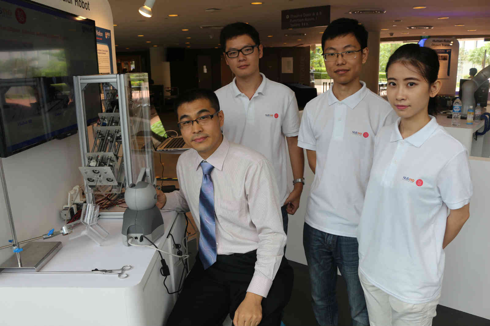
(9 April 2015) We have been invited to demonstrate our Intelligent Tubular Robotic System (iTubot) at the exhibition showcasing NUS’ contribution to nation-building through groundbreaking research. The event launched at the University Cultural Centre on 9 April to celebrate the 50th birthday of Singapore and the 110th birthday of NUS.
Our Intelligent Tubular Robotic System can potentially assist with minimally invasive procedures and is also endowed with intelligent navigation capabilities, which receives much attention during the event.
www.mech.hku.hk/bse/bbse3002
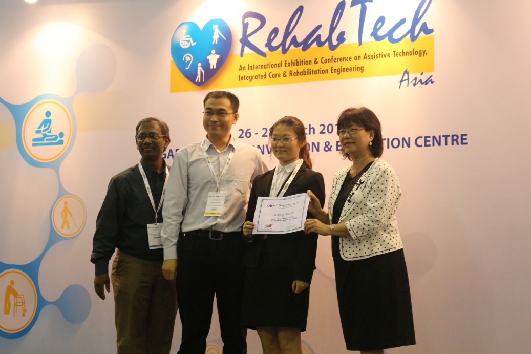
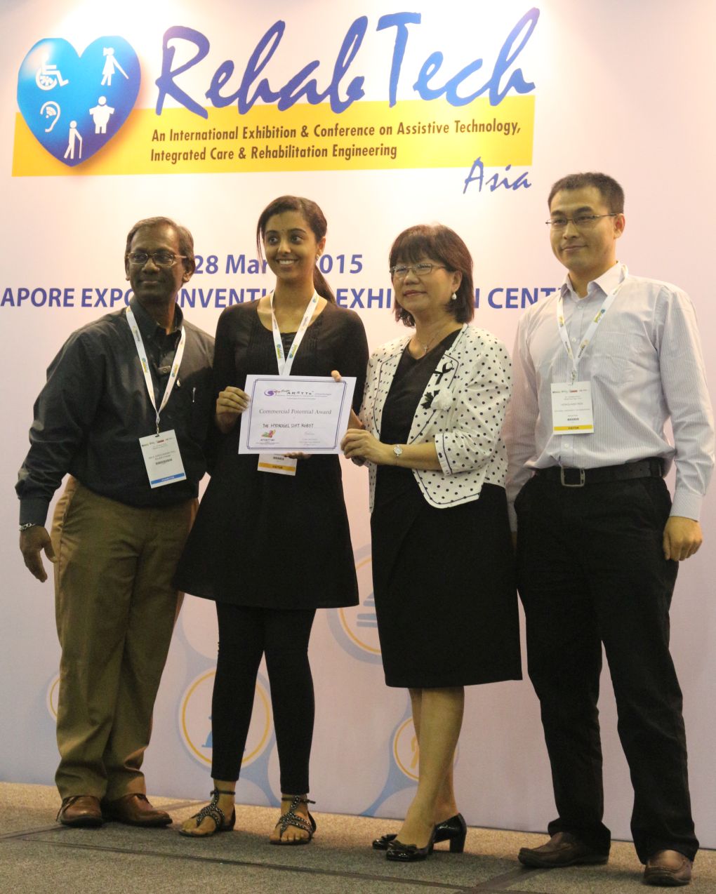
(Mar, 2015) In the recent Asia Pac AR&TTs challenge 2015, our project on a soft robotic system for oral intervention (team members: Neera, Yi, Hongliang) won the Commercial Potential Award and the project on magnetic actuated robotic intervention (team members: Shen Shen, Zhu Jingling, Song Shuang, Li Jun, Loh Kai Ting, Ren Hongliang) won the Pitching Award.
BN5209 Neurosensors and Signal Processing Semester 2, 2014/2015
Time period: 14-Jan-14 To 9-May-14
Lecture Time:
1. EEG for brain state monitoring
2. EEG/EMG Feature Identification during Elbow Flexion/Extension
This module teaches students the advanced neuroengineering principles ranging from basic neuroscience introduction to neurosensing technology as well as advanced signal processing techniques. Major topics include: introduction to neurosciences, neural recording methods, neural circuits, amplifiers, telemetry, stimulation, sensors for measuring the electric field and magnetic field of the brain in relation to brain activities, digitization of brain activities, neural signal processing, brain machine interfaces, neurosurgical systems and applications of neural interfaces. The module is designed for students at Master and PhD levels in Engineering, Science and Medicine.
Basic probability
Basic circuits
Linear algebra (matrix/vector)
Matlab or other programming
Recommended Textbooks: Neural Engineering, Edited by Bin He
Seminar papers
The majority of the course will be in lecture-tutorial format. Some advanced topics will be in the formats of seminar and research presentations.
Take Home Tests (5 for 50%)
Labs/Projects Reports + Presentations (2 for 20%)
Seminars (1 for 10%)
Take Home Final Exam(20% )
<!–
–>
This is a local copy of the website: http://flexidiamond.blogspot.sg/


From Left: Mr Teo Jing Chun, Dr Ren Hongliang, Mr Un Weiyang, Miss Soh Yan Bing, Mr Ong Jun Hao Edmund
Foreground: Mr Yeow Bok Seng
Note: For your convenience, the following announcements are exactly extracted from IVLE and a PDF version is also attached here: IVLEAllAnnouncements.pdf
| by: Aneel Kumar Maheshwari, 31-Oct-2014 11:19 AM. |
IVLE: BN3101: BN3101 Director’s Award
|
| Dear students,This award is given to the group that shows that this module has a significant impact in the working relationship of the group and the learning process of the individual team members.How is this Award being judged? Each group is to submit a one page write-up of less than 500 words on how this module has benefited the group in general and how it has changed individual members’ views on design of medical device. A general description of your experience would be most appropriate.You will be judged by: Your mentors’ perception of the positive impact this course has on your education and your relationship with your peers.Submit by: 10:00am Monday the 03 Oct 2014. Please send to Dr. LEO Hwa Liang (bielhl@nus.edu.sg) with the following subject title: BN3101 – Director’s Award Group X where X is your group number. Will we be graded on the write-up? No, you will not be graded on this write-up. This is an optional submission by the group. Will any of the awards affect my grade? None of the awards will affect your grades. Regards, Aneel Kumar |
| by: Aneel Kumar Maheshwari, 31-Oct-2014 09:44 AM. |
IVLE: BN3101: Reminder: submit team Presentation (20min and 5min) onto IVLE Final oral Presentation
|
| Dear BN3101 Studens:Reminder to submit your team presententation ( 20 mins + 5 mins ) onto IVLE Final oral Presentation folder by 23:59 Sunday, 2nd Nov 2014.Regards, Aneel Kumar |
| by: Aneel Kumar Maheshwari, 28-Oct-2014 03:32 PM. |
IVLE: BN3101: BN3101 Oral Presentation Room Booking (Morning and After session) |
| Presentation to the individual supervisor in individual classroom (morning):EA-02-11 (9am to 12pm): Dr. Leo Groups (12-13) EA-02-14 (9am to 12pm): Prof. Casey Chan Groups (1-3) E1-06-04 (9am to 12pm): Dr. Ren Hong Liang Groups (4-6) E1-06-06(9am to 12pm): Dr. James Kah Groups (7-9) E1-06-14 (9am to 12pm): Dr. Michael Girard Groups (10-11)Schedule for the Final Afternoon Presentation for top teams Announce the top team ONLY then. Start at 1:30pm – 2:15pm EA-02-11Refreshment: 2:15pm to 2:30pmPresentation of awards: 2:30pm |
| by: Aneel Kumar Maheshwari, 28-Oct-2014 02:58 PM. |
IVLE: BN3101: BN3101 Final Oral Presentation (03 Nov 2014 on Monday) |
| Presentation to the individual supervisor in individual classroom (morning):1. Each team present 20 mins + 5-10 mins Q&A. Each presentation may divide the presentation in two or three sections. Please submit onto IVLE Final oral Presentation folder by 23:59 Sunday 2ndNov the following list:The students are allowed to decide how many sections are there in their presentation and which section they want to present in. For two sections: First Section – 1st Member, 2nd Member, 3rd Member Second Section – 4th Member, 5th Member, 6th Member OR For three sections: First Section – 1st Member, 2nd Member Second Section – 3rd Member, 4th Member Third Section – 5th Member, 6th Member For teams having less than 6 members, any of the sections may have one member less. The presenter will be announced at the time of presentation. Guidelines for presentation: Your presentation must conform to the following: a. Each group is strictly given 30 min inclusive of Presentation (20 min), Q & A (5-10 min), and Change over (1 min). b. When your .ppt file is ready, you may upload it onto the IVLE Final Oral Presentation folder c. Your .ppt file must be submitted by 23:59 Sunday 2nd Nov. d. You are to submit a 20 minutes presentation power point and 5 minutes abbreviated presentation (in case you are the finalist for the afternoon session). e. All .ppt file must conform to the following format: Group X 30 mins Presentation.ppt (X is the Group Number) Group X 5 mins Presentation.ppt The 5 minutes presentation in the afternoon should not include video. For presentation to the individual supervisors, please check with your individual supervisor whether video can be included in the presentation. Schedule for the Final Morning Presentation The sequence of presentation will be up to the supervisor to decide. Suggested start time 9:00 am and end around 12:00pm in individual classroom Schedule for the Final Afternoon Presentation for top teams Student can decide who to present. Announce the top team ONLY then. Start at 1:30pm – 2:15pm EA-02-11 2:30pm pm Presentation of awards (15 minutes) The following prizes will be given out: 1. Most Innovative Design 2. Most Elegant Instrumentation (Aesthetic and Ergonomic) 3. Most Fundable Design 4. Best Presentation 5. The Prestigious Director’s Award (voted by lecturers and mentors) The winners of ‘Most Innovative Design’, ‘Most Elegant Instrumentation (Aesthetic and Ergonomic)’ and ‘Most Fundable Design’ will be chosen by means of votes casted by the students, lecturers and mentors. These awards are not graded 3pm Refreshments and Interaction session Attendance: All team members must be present throughout their afternoon session Final Presentation (Top 5 finalist). Attendance will be taken and 0.5 points will be deducted for each team member absent during their respective sessions. You are welcome to attend part or all of the other sessions. Reports Submission All teams have to submit the hard copy reports after the final presentation itself (Friday, 14th November 2014 before 5pm) to Aneel Kumar (Bio-design Lab E3-05-05). A penalty of 1 point will be imposed for each day of late submission of individual report. Please submit soft copy of your report and actual prototype to your respective supervisor. Regards, Aneel Kumar |
| by: Aneel Kumar Maheshwari, 27-Oct-2014 03:18 PM. |
IVLE: BN3101: Peer Assessment 2014 |
| Dear BN3101 Students,The peer assessment exercise is conducted for students to assess their group members’ individual contribution to the project. For each review item you can grade your fellow group members from 0 to 10 by following a general marking standard of:0 = extremely poor; 6 = average; 8 = good; 10 = excellent.To do the peer assessment, please follow the steps of: go to the BN3101 IVLE webpage –> click Project –> click View –> click Project Evaluation (on the left) –> Select Peer Assessment 2014 –> click Evaluate –> Evaluate your other group members one by one.Please do not routinely assign a high score as this will result in an average score for everyone. For this to work you have to give an honest assessment of your peers. The purpose of the peer assessment is to make minor adjustment within the group. Your peer assessment rating will not affect other groups. And the rating by individual students is confidential and will not be made known to other group members. Please complete the Peer Assessment 2014 by 14th Nov 2014 (Friday), 11:59pm; failure to do so, your group members’ project marks based on “team effort” will be affected. Regards, Aneel Kumar |
| by: Leo Hwa Liang, 09-Oct-2014 04:15 PM. |
New Files in Workbin – BN3101 : BIOMEDICAL ENGINEERING DESIGN – 2014 |
New Files :Folder Name : Lecture NotesFilename: Bioethics and Medical Device.pdf Description: BN3101 – Bioethics and Medical DevicesClick on the filename to download the file. |
| by: Leo Hwa Liang, 03-Oct-2014 09:32 AM. |
New Files in Workbin – BN3101 : BIOMEDICAL ENGINEERING DESIGN – 2014 |
New Files :Folder Name : Lecture NotesFilename: Sterility 2014.pdf Description: BN3101 – SterilityFilename: GMP-GLP 2014.pdf Description: BN3101 – GMP – GLPClick on the filename to download the file. |
| by: Leo Hwa Liang, 22-Sep-2014 09:02 PM. |
New Files in Workbin – BN3101 : BIOMEDICAL ENGINEERING DESIGN – 2014 |
New Files :Folder Name : Lecture NotesFilename: Quality_System_Template_2014.pdf Description: BN3101 – Quality templateClick on the filename to download the file. |
| by: Leo Hwa Liang, 12-Sep-2014 11:53 AM. |
New Files in Workbin – BN3101 : BIOMEDICAL ENGINEERING DESIGN – 2014 |
New Files :Folder Name : Lecture NotesFilename: Review of Regulatory Issues 2014.pdf Description: BN3101 – Regulatory Affairs lectureClick on the filename to download the file. |
| by: Leo Hwa Liang, 08-Sep-2014 12:21 PM. |
IVLE: BN3101: BN3101 – Accessing ASTM standards in NUS central library |
| Dear ASTM students,NUS central library hold the ASTM standards, in hardbound (1998 and before) and DVD formats. You will need to sign in for the access of these standards. Remember to bring your thumbdrive to copy the relevant standards.You will not be able to access and download the ASTM standards from the internet as we need to pay to do so.Regards, Leo |
| by: Leo Hwa Liang, 08-Sep-2014 10:56 AM. |
New Files in Workbin – BN3101 : BIOMEDICAL ENGINEERING DESIGN – 2014 |
New Files :Folder Name : AssignmentsFilename: ASTM Assignments 2014.pdf Description: BN3101 – For ASTM students only, ASTM assignmentsClick on the filename to download the file. |
| by: Leo Hwa Liang, 04-Sep-2014 09:22 AM. |
New Files in Workbin – BN3101 : BIOMEDICAL ENGINEERING DESIGN – 2014 |
New Files :Folder Name : Lecture NotesFilename: Introduction to the ASTM 2014.pdf Description: BN3101 – ASTMClick on the filename to download the file. |
| by: Casey Chan (Ortho), 01-Sep-2014 09:53 PM. |
IP Lecture II |
| There is a live lecture on Monday 8 Sept from 10am to 12 noon at EA 02-11.Please see http://www.biodsign.org/home/iplectureii |
| http://www.biodsign.org/home/iplectureii |
| by: Leo Hwa Liang, 29-Aug-2014 04:04 PM. |
New Files in Workbin – BN3101 : BIOMEDICAL ENGINEERING DESIGN – 2014 |
New Files :Folder Name : Lecture NotesFilename: Risk Management 2014.pdf Description: BN3101 – Risk managementFilename: Design Rationale and Design Verification 2014.pdf Description: BN3101 – Design Rationale and Design VerificationClick on the filename to download the file. |
| by: Leo Hwa Liang, 29-Aug-2014 03:59 PM. |
New Files in Workbin – BN3101 : BIOMEDICAL ENGINEERING DESIGN – 2014 |
New Files :Folder Name : Lecture NotesFilename: Risk Analysis Table.docx Description: BN3101 – Risk analysis tableClick on the filename to download the file. |
| by: Leo Hwa Liang, 25-Aug-2014 04:44 PM. |
New Files in Workbin – BN3101 : BIOMEDICAL ENGINEERING DESIGN – 2014 |
New Files :Folder Name : Lecture NotesFilename: Design Analysis Tutorial.pdf Description: BN3101 – Design Analysis slidesClick on the filename to download the file. |
| by: Aneel Kumar Maheshwari, 21-Aug-2014 12:00 AM. |
Design Analysis Exercise ( Divided in Two time Slots) |
| Dear BN3101 Students,Design Analysis Exercise will be divided into two time Slots.Slot 1: (Group 1 – Group 7) and time : 1pm to 2pm on 25 August 2014 at EA-02-11 Slot 2: (Group 8 – Group 13) and time: 2pm to 3pm on 25 August 2014 at EA-02-11Reagrds, Aneel Kumar |
| by: Aneel Kumar Maheshwari, 20-Aug-2014 12:00 AM. |
BN3101 booking of machines in the design studio |
| Dear BN3101 supervisors,This semester both BN3101 and BN2103 will be using the Design Studio.To avoid problems, we set up an online booking system accessible (within NUS or VPN) at:http://172.18.53.85/bmebooking/ This applies to all the “workshop” machines in the lab like mill, lathe, saw, etc (not the Instron). Please let your students know that if they want guaranteed time on the machine they will need to book. Students who booked the machine will have top priority in using the machine during the booked time slot. The following restrictions on bookings apply (the system automatically detects violations of the rules ): – Each single booking can last no more than 2 hours – Each student can book a maximum of 4 hours per week per machine Each BN3101 group will have an account with username BN3101_X (where X is the group number). Password is the same as the user name. Students may change it from the system later if they want to. Kindly contact with Aneel, so he can creates the account for your groups. Regards, Dr. Leo |
| by: Michael Girard, 12-Aug-2014 04:31 PM. |
New Files in Workbin – BN3101 : BIOMEDICAL ENGINEERING DESIGN – 2014 |
New Files :Folder Name : Groups 10-11Filename: BN3101 Iris Expander – Groups 10-11.pdf Description: For Groups 10&11: Iris Expander – Project Description and General InfosClick on the filename to download the file. |
| by: James Kah, 11-Aug-2014 03:36 PM. |
| New Files in Workbin – BN3101 : BIOMEDICAL ENGINEERING DESIGN – 2014 |
New Files :Folder Name : Group 7 to 9Filename: 140809 Consumer Diagnostics – Project Introduction.pptx Description:Filename: BN3101-Timetable_2014.xls Description:Filename: Quality_System_Template_2012.pdf Description:Click on the filename to download the file. |
| by: Casey Chan (Ortho), 11-Aug-2014 12:00 AM. |
| IP Lecture I |
| This is the first of two lectures on Intellectual Properties. The link for the lecture and the accompanying notes is here. http://www.biodsign.org/lectures. The 2nd lecture is scheduled for early Sept. |
| by: Leo Hwa Liang, 08-Aug-2014 03:44 PM. |
| IVLE: BN3101: Uploading of Introduction to BN3101 slides |
| Dear students, I have just uploaded the introduction slides for the Monday BN3101 orientation. This is the first of a series of online lectures throughout this semester.Regards, Leo |
| by: Aneel Kumar Maheshwari, 07-Aug-2014 02:15 PM. |
| BN3101 Groups |
| Dear Students,Welcome to BN3101 students.A Gentle reminder for BN3101 orientation lecture on Monday at 10am (EA-02-11) and also you can see the project supervisors and groups on IVLE.See you all soon. Regards, Dr. Leo |
Note:
For teaching purpose, this page is listing related flexible manipulators, which are cited from related websites.
An incomplete comparison table FYI ListOfFlexibleManipulators.pdf
designs and manufactures snake-arm robots, which are specifically designed to perform remote handling operations in confined and hazardous spaces. OC Robotics has delivered robots for industries spanning – amongst others – nuclear, aerospace, medical and security. It has also provided consultancy and analysis services for these sectors.
Features: Snake-arm robots have a long, slender and flexible design, fitting effortlessly through small openings and around obstacles. Snake-arm robots do not need support from the environment, which means that they can navigate through an open space, avoiding obstacles, carrying tools and conducting work.
Amazing mechatronics from the SAMSUNG Electronics people for a NOTES structure. Significantly more advanced that the KAIST robot presented before. (A 2013 video of the system.)
Intuitive Surgical receives FDA clearance, unveils da Vinci Sp system.
Full story: While the FDA has already given clearance to the system, Intuitive Surgical plans to hold off on releasing it to market until it’s been made fully compatible with the latest da Vinci Xi robot.
Note: our NUH cardiac surgeons preferred this system for their epi-cardiac procedures!
The Olympus EndoEye Flex 5 offers HD resolution in a 5 mm diameter scope. The device uses digital-chip technology to place the camera on the tip of the scope, delivering high-quality, bright images and enabling doctors to see fine details during surgical procedures. Additionally, the scope allows for 100-degree angulation in all directions.
The CorPath Vascular Robotic System enables the precise, robotic-assisted control of coronary guidewires and balloon/stent devices.
Excellent pneumatic actuated flexibility!
SPL with bi-manual control capability.
JAiMYTM, the first motorized articulating laparoscopic instrument with iD-intelligent Dexterity, is designed to enable surgeons to overcome the unique challenges presented by single incision and conventional laparoscopic surgery.
Richard Wolf Urology flexible endoscope “cobra” & laser for stone management: the first dual channel uretero renoscope
This project aims to develop a flexible manipulator for transnasal/transoral surgery. Compared with existing surgical manipulators, the developed one should have better performance in workspace and dexterity, thus better facilitate the surgical operation.
A constrained tendon-driven serpentine manipulator (CTSM) is designed as shown in Figure 1. It includes an underactuated tendon-driven flexible section, a constraint and a set of tendons. The tendon-driven flexible section is similar to our previous wire-driven robot arm design. It comprises of several identical vertebras, and an elastic tube. Two successive vertebras form a joint and the joint rotation follows the elastic tube bending. Four tendons pass through all the vertebras. For each tendon, the two ends are attached to the distal vertebra and the motor respectively. These tendons are grouped to two pairs and are orthogonally arranged as shown in Figure. 1 (b). One tendon pair controls the bending about X axis and the other tendon pair controls the bending about Y axis. The manipulator bending is planar. The bending angle and bending direction are controlled by the motion of the four tendons. The constraint can be an elastic tube or rigid tube. The constraint translates along the tendon-driven flexible section. Vertebras in the range of the constraint are confined and vertebras out of the range of the constraint are free of rotation. Thus, the last constrained vertebra serves the base of the bending section.

Figure 1 3D design of the CTSM: (a) the assembled and explosion view of the CTSM; (b) the tendon configuration; (c) the cross section view of the joint.
The bending motion of the manipulator is shown in Figure 2: when the insertion of the constraint is 0, the CTSM bends by the tendons as a traditional TSM. By pushing the constraint forward the backbone is segmented to two parts: the proximal constrained section and the distal free bending section. Compared to the distal free bending section, the proximal constrained section is stiffer and the joints’ rotations are smaller. By pushing and pulling the constraint, the lengths of the two sections are controlled.

Fig. 2 Bending motion illustration: (a) the bending section is not constrained; (b) part of the bending section is constrained; (c) the whole bending section is constrained.
A prototype is built as shown in Figure 3. In the prototype, the flexible backbone has 27 vertebras. The vertebras are fabricated by 3D printing, and the material used is plastic. Each joint can rotate up to 7.25°.The total length of the flexible backbone is 104mm, and the diameter is 7.5mm. A silicon rubber tube serves the elastic tube. The outer diameter is 3 mm and inner diameter is 2 mm. Four steel wires with nylon coating are used to control the backbone bending. The diameter of the steel is 0.3 mm. The wires are arranged orthogonally, with opponent wires make a pair. Each wire pair is connected to a drum wheel. The rotation of the drum wheel is controlled by a servo motor. The diameter of the drum wheel is 50 mm. The wires are guided by a Teflon tube, whose outer diameter is 0.9 mm and inner diameter is 0.5 mm. The replaceable constraint is hold by a chuck, which is mounted on the linear actuator. The range of the linear actuator is 100 mm.
By changing the stiffness ratio between the flexible bending section and the overall stiffness λ, the workspace of the CTSM is as shown in Figure 4. In the simulation the length of the CTSM is 100 mm, and the number of vertebrae is 25.

Fig. 4 workspace comparison: (a) traditional TSM; (b) CTSM with elastic constraint; (c) CTSM with elastic constraint; (d) CTSM with rigid constraint.
When the CTSM with a rigid constraint is attached to a mobile base, the workspace and dexterity distribution are shown in Figure 5. For the tendon-driven serpentine manipulator (TSM), the dexterity is indexed as the kinematic flexibility. For a traditional TSM, the kinematic flexibility is 1 in most places; the maximum is 2. For the designed CTSM, the kinematic flexibility is enhances all over the workspace and the maximum is 15.

Figure 5 Comparison of the dexterity distribution over the workspace: (a) traditional TSM; (b) CTSM with λ=0.
Staff: Zheng Li
Visiting Students: Gui Fu, Zhengchu Tan, Jan Feiling
PIs: Hongliang Ren and Haoyong Yu
– Phantom tests
– CTSM Experiments in ex-vivo hearts and phantoms (2014/11/22)
1. Zheng Li, Haoyong Yu and Hongliang Ren, “A Novel Constrained Tendon-driven Serpentine Manipulator (CTSM)”, ICRA 2015 (under review)
2. Zheng Li, Haoyong Yu and Hongliang Ren, “A Novel Underactuated Wire-driven Flexible Robotic Arm with Controllable Bending Section Length”, ICRA 2014 Workshop on Advances in Flexible Robots for Surgical Interventions, Hong Kong, May 31-June 7, 2014
3. Zheng Li, Ruxu Du, Haoyong Yu and Hongliang Ren, “Statics Modeling of an Underactuated Wire-driven Flexible Robotic Arm”,IEEE BioRob 2014, Sao Pauo, Brazil, Aug12-15, 2014
<!–

Fig. 3 CTSM prototype.
.–>
