For more information, please visit the workshop homepage: https://sites.google.com/view/iros-2025-c4sr/


For more information, please visit the workshop homepage: https://sites.google.com/view/iros-2025-c4sr/
IEEE Access 2017
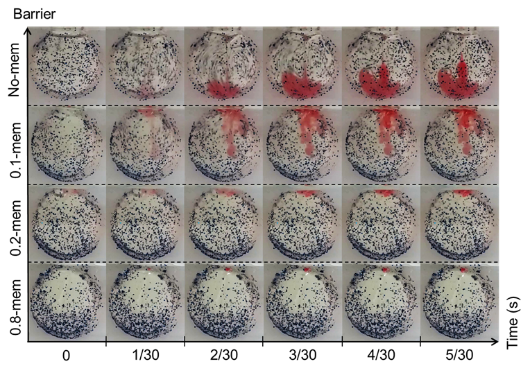
The fear of pain and needles deter some patients from seeking intravitreal treatment, which drives our group to develop an needleless device for performing intravitreal injections. A prototype for an electro-magnetically actuated needleless injector, based on Halbach arrays, is described and characterized in a lab setting. The implication of the prototype for needleless ocular drug delivery is investigated. This investigation is intended to eventually improve drug delivery of glaucoma medication enabling safe needleless approaches. We detail the design aspects of the injector and characterized the device with custom-made phantoms. It was observed that, despite delivering the drug bolus to the center, the viscous vitreous phantom indicated vorticities similar to counter rotating vortex pairs, which could damage the retina. The observed peak velocity during the phantom experiments was 6.1mm/sec at the retinal layer, indicating that the delivery bolus can impart shear forces to the retina via the vitreous.
> 1-minute short video demo
> full video demo
The results comparing the measured Fz, the force in the normal direction to the sensor surface, and Mag, the magnitude of the force vector, across the various depths of injection and at the two voltage points.

Fig 24. Left (15V) Right (20V); Top (Fz) Bottom (Mag)
Comparison between the four depths did not show significant differences:
Changing the distances between the sensor surface and the injection nozzle does not appear to have a distinguishable relationship. Note: each data plot is the average from 3 data samples. This is indicative of the following; regardless of the size of the orbital, the peak force observed is going to be dependent on the injectant properties. We note that more experiments should be done for characterization of distances between 20mm and 12.5mm, we did not test this range due to concerns over damaging the sensitive ATInano17, and hence the initial expectation of measuring 20 to 35mm and anticipating an extrapolate-able relationship. The rational for these distances assumes an orbital diameter of 25mm and the drug is delivered to the center at 12.5mm. The 25mm distance is likely to be near the retinal layer and 20mm would be in between.
Test in phantom chamber:
The dimension of the vitreous phantom chamber is a cylinder with height 17mm and diameter of 25mm. This relates to a volume of approximately 8345uL. This is significantly larger than the vitreous volume in human eyes. Assuming the human vitreous to be 4000uL, the height of our cylinder should be 8mm. In such a scenario, the rotational symmetry in the spherical orbital is lost and hence the flow will be more a keen to a 2D planar flow rather than a 3D flow. Our selection of 17 mm was a compromise between maintaining the 3D flow while allowing an observable 2D slice of the injection profile. In addition, the selection of the 10.9 mm by 17 mm access point is arbitrary. Its purpose was to allow ease of filling and removal of vitreous phantom while maintaining the spherical shape as much as possible. The current dimensions relates to a chord at 11.25mm from the center of the circle, thus maintaining at least 95% of the diameter.
Electromagnetic needleless injector with halbach array towards intravitreal delivery (in press) IEEE Access, 2017
IEEE ACCESS. PREPRINT VERSION. ACCEPTED Dec, 2017
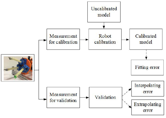
Abstract—Soft robotics is a research field growing rapidly with primary focuses on the prototype design, development of soft robots and their applications. Due to their highly deformable features, it is difficult to model and control such robots in a very precise compared with conventional rigid structured robots. Hence, the calibration and parameter identification problems of an underactuated robotic hand with soft fingers are important, but have not been investigated intensively. In this paper, we present a comparative study on the calibration of a soft robotic hand. The calibration problem is framed as an AX=YB problem with the partially known matrix A. The identifiability of the parameters is analyzed, and calibration methods based on nonlinear optimization (i.e., L-M method and interior-point method) and evolutionary computation (i.e., differential evolution) are presented. Extensive simulation tests are performed to examine the parameter identification using the three methods in a comparative way. The experiments are conducted on the real soft robotic-hand setup. The fitting, interpolating, and extrapolating errors are presented as well.

A tele-operated robotic catheterization system can significantly alleviate the surgeons from radiation exposure and fatigue resulted from long standing time with protective suits. Proximal force/torque signals imply the critical information about the contact forces between the catheter and its surrounding structures. This paper presents a compact, cost-effective force and torque sensing device suitable for catheterization procedures to measure the proximal force/torque signals of the input catheter. The device consists of a rotatable and linear retractable mechanism, a laser mouse sensor, and a coil spring. As the stretched, compressed, and twisted values vary due to the sliding joint, the force and torque signals can be computed based on the Hooke’s law. The proposed sensing device has many advantages such as cost-effective, easily miniaturized and customized, and can be extended to the MRI compatible sensors. The experimental results with step response and time-varying loads by comparing to an ATI Nano17 force/torque sensor show that the Root Mean Squared Error (RMSE) for force and torque measurement are 0.042 N and 0.228 mNm respectively.

J. Guo; M. Li; P. Ho & H. Ren Design and Performance Evaluation of a Force/Torque Sensor for Tele-operated Catheterization Procedures IEEE Sensors Journal, 2016, PP, 1-8
Background: Accurate motion control of flexible surgical manipulators is crucial in tissue manipulation tasks. Tendon-driven serpentine manipulator (TSM) is one of the most widely adopted flexible mechanisms in MIS for its enhanced maneuverability in torturous environment. TSM, however, exhibits high nonlinearities and conventional analytical kinematics model is insufficient to achieve high accuracy.
Methods: To account for the system nonlinearities, we applied data driven approach to encode the system inverse kinematics. Three regression methods: Extreme Learning Machine (ELM), Gaussian Mixture Regression (GMR) and K-Nearest Neighbors Regression (KNNR) were implemented to learn a nonlinear mapping from the robot 3D position state to the control inputs.
Results: The performance of the three algorithms were evaluated both in simulation and physical trajectory tracking experiments. KNNR performs the best in the tracking experiments with the lowest RMSE of 2.1275mm.
Conclusions: The proposed inverse kinematics learning methods provide an alternative and efficient way to accurately model the challenging tendon driven flexible manipulator.
Keywords: Tendon-driven serpentine manipulator; surgical robotics; Inverse kinematics; Heuristic Methods

Ultrasound imaging procedures are deemed as one of the most convenient and least invasive medical diagnostic imaging modalities and have been widely utilized in health care providers, which are expecting semiautomatic or fully-automatic imaging systems to reduce the current clinical workloads. This paper presents a portable and wearable soft robotic system which has been designed with the purpose of replacing the manual operation to cooperatively steer the ultrasound probe. This human-compliant soft robotic system, which is equipped with four separated parallel soft pneumatic actuators and is able to achieve movements in three directions. Vacuum suction force is introduced to attach the robot onto the intended body location. The design and fabrication of this soft robotic system are illustrated. To our knowledge, this is the first body-attached soft robot for compliant ultrasound imaging. The feasibility of the system is demonstrated through proof-of-concept experiments.

Developing a wearable soft robotic system (Figure 1), which is capable of mimicking the procedure of probe steering and optimizing the contact force and angle according to the specific conditions, has great significance of reducing the reliance of the ultrasound imaging on the experience of operators and obtaining images with high quality.
PhD Student: Xiaoyi Gu
FYP Student: Koon Lin Tan
Project Investigator: Hongliang Ren
Ren, H.; Gu, X. ; Tan, K. L. Human-Compliant Body-Attached Soft Robots Towards Automatic Cooperative Ultrasound Imaging 2016 20th IEEE International Conference on Computer Supported Cooperative Work in Design (CSCWD 2016), IEEE, 2016, –


no images were found


![wpark_large[1]](http://bioeng.nus.edu.sg/mm/wp-content/uploads/2015/06/wpark_large1.jpg)

The objectives of this project are to design and evaluate the performance of an electromagnetic actuated (EMA) drug delivery system and explore the related issues.
The EMA system consists of magneto-responsive microcapsules as drug carriers, a coil system with controlled currents flowing through, as well as a tracking algorithm for close loop feedback control.
The magneto-responsive and thermal sensitive microcapsules are prepared through an encapsulator. The properties can be further utilized for controlled drug release. The encapsulated microbubbles are prepared based on a gas foaming technique for enhancing the ultrasound imaging contrast.
The coil system consists of 2 Helmoholz coil pairs and 2 Maxwell coil pairs are fabricated with printed aluminum skeleton and copper wires. A current control system including 3 DC motor governors and a USB to RS485 converter are added to realize programmable current control. Hence, the magnetic fields generated by the coils are controlled by the signals sent by the computer. Figure 1 shows the principle of actuation over the microcapsules.

Fig. 1: Principle of Magnetic Actuation over the Microcapsules
Figure 2 shows the preliminary set up for actuation over microparticles within the region of interest.

Fig. 2 Setup for Microparticles Actuation
Microcapsules with evenly distributed magnetic stripes have been fabricated. The stripes make the spherical microcapsules asymmetric so that their locomotion control is directed. Alignment and movement of the microcapsules are observed in the EMA system under DC output, while rotation is observed under sinusoidal output current.

Fig. 3 Microcapsules with magnetic CI strips. Scale bar: 200μm.

Fig.4 Magnetic actuation with (A)small cylindrical magnet and (B)magnetic microcapsules
Staff: Shen Shen, Song Shuang and Zhu Jingling
PIs: Ren Hongliang and Li Jun
1.Shen Shen, Shuang Song, Jingling Zhu, Max Q-H Meng, Jun Li and Hongliang Ren, Preliminary Design towards a Magnetic Actuated Drug Delivery System, 7th IEEE International Conference on Cybernetics and Intelligent Systems and the 7th IEEE International Conference on Robotics, Automation and Mechatronics, 2015.

Multi-robot co-manipulation shows great potential to address the limitations of using single robot in complicated tasks such as robotic surgeries. However, the dynamic setup poses great uncertainties in the circumstances of robotic mobility and unstructured environment. Therefore, the relationships among all the base frames (robot-robot calibration) and the relationships between the end-effectors and the other devices such as cameras (hand-eye calibration) and tools (tool-flange calibration) have to be determined constantly in order to enable robotic cooperation in the constantly changing environment. We formulated the problem of hand-eye, tool-flange and robot-robot calibration to a matrix equation AXB=YCZ. A series of generic geometric properties and lemmas were presented, leading to the derivation of the final simultaneous algorithm. In addition to the accurate iterative solution, a closed-form solution was also introduced based on quaternions to give an initial value. To show the feasibility and superiority of the simultaneous method, two non-simultaneous methods were also proposed for comparison. Furthermore, thorough simulations under different noise levels and various robot movements were carried out for both simultaneous and non-simultaneous methods. Experiments on real robots were also performed to evaluate the proposed simultaneous method. The comparison results from both simulations and experiments demonstrated the superior accuracy and efficiency of the simultaneous method.
Measurement Data:
Homogeneous transformations from the robot bases to end-effector (A and C), and from tracker to marker (B).
Unknowns:
Homogeneous transformations from one robot base frame to another (Y), and from eye/tool to robot hand/flange (X and Z).
The measurable data A, B and C, and the unknowns X, Y and Z form a transformation loop which can be formulated as, AXB=YCZ (1).

Fig. 1: The relevance and differences among the problem defined in this paper and the other two classical problems in robotics. Our problem formulation can be considered as a superset of the other two.
3-Step Method
In the non-simultaneous 3-Step method, the X and Z in (1) are separately calculated as two hand-eye/tool-flange calibrations which can be represented as an AX = XB problem in the first and second steps. This results in two data acquisition procedures, in which the two manipulators carry out at least two rotations whose rotational axes are not parallel or anti-parallel by turns while the other one being kept immobile. The last unknown robot-robot relationship Y could be solved directly using the previously retrieved data by the method of least squares.
2-Step Method
The non-simultaneous 2-Step method formulates the original calibration problem in successive processes which solve AX = XB firstly, and then the AX = YB. The data acquisition procedures and obtained data are the same with the 3-Step method. In contrast to solving robot-robot relationship independently, the 2-Step method solves tool-flange/hand-eye and robot-robot transforms in an AX = YB manner in the second step. This is possible because equation AXB = YCZ can be expressed as (AXB)inv(Z) = YC, which is in an AX = YB form with the solution of X known.
Non-simultaneous methods face a problem of error accumulation, since in these methods the latter steps use the previous solutions as input. As a result, the inaccuracy produced in the former steps will accumulate to the subsequent steps. In addition to accuracy, it is preferred that the two robots participating the calibration procedure simultaneously, which will significantly save the total time required.
In regards to this, a simultaneous method is proposed to improve the accuracy and efficiency of the calibration by solving the original AXB = YCZ problem directly. During the data acquisition procedure, the manipulators simultaneously move to different configurations and the corresponding data set A, B and C are recorded. Then the unknown X, Y and Z are solved simultaneously.
To illustrate the feasibility of the proposed methods, intensive simulations have been carried out under different noise situations and by using different numbers of data sets.

Fig. 2: A schematic diagram which shows the experiment setup consisting of two Puma 560 manipulators, a tracking sensor and a target marker to solve the hand-eye, tool-flange and robot-robot calibration problem.
For the rotational part, the three methods perform evenly in the accuracy of Z. However, the simultaneous method slightly outperforms in the accuracy of X and significantly in the accuracy of Y than the other two non-simultaneous methods. The results of the translational part are similar to the rotational ones. For the solution of Z, the accuracy of the simultaneous method is as good as the 3-Step method but slightly worse than the 2-Step method. However, the simultaneous method achieves a significantly improvement in the accuracy of X and Y compared to the other two methods.


Besides the simulation, ample real experiments have been conceived and carried out under different configurations to evaluate the proposed methods. As shown in Fig. 6, the experiments involved a Staubli TX60 robot (6 DOFs, averaged repeatability 0.02mm), a Barrett WAM robot (4 DOFs, averaged repeatability 0.05mm) and a NDI Polaris optical tracker (RMS repeatability 0.10mm). The optical tracker was mounted to the last link of the Staubli robot, referred to as sensor robot. The corresponding reflective marker was mounted to the last link of the WAM robot, referred to as marker robot.

Fig. 6: The experiment is carried out by using a Staubli TX60 robot and a Barrett WAM robot. A NDI Polaris optical tracker is mounted to the Staubli robot to track a reflective marker (invisible from current camera angle) that is mounted to the WAM robot.
To demonstrate the superiority of the simultaneous method in the real experimental scenarios, a 5-fold cross-validation approach is implemented for 200 times for all the calibration methods under all system configurations. For simultaneous method, after data alignment and RANSAC processing, 80% of the remaining data are randomly selected to calculate unknown X, Y, and Z, and 20% are used as test data to evaluate the performance. For 2-Step and 3Step methods, after calculating the unknowns by each method, same test data from the simultaneous method are used to evaluate their performances.
In Fig. 7, the evaluated errors of 200 times 5-fold cross-validation for three proposed methods at three ranges are shown as box plots. Left-tail paired-samples t-tests have been carried out to compare the performances of simultaneous method versus 2-Step and 3-Step methods, respectively. The results indicate that the rotational and translational errors from the simultaneous method are very significantly smaller than the 2-Step and 3-Step methods. Only two non-significant results exist in the rotational performances at medium and far ranges when comparing the simultaneous method with the 3-Step one. Nevertheless, the simultaneous method outperforms the non-simultaneous ones for translation error at all ranges.

Fig. 7: Results of 200 times 5-fold cross-validation and left-tail paired-samples t-test at the near, medium and far ranges. The box plots show the rotational and translational error distributions for three methods at three ranges. **, * and N.S. stands for very significant at 99% confidence level, significant and non-significant at 95% confidence level.
1. Liao Wu, Jiaole Wang, Max Q.-H. Meng, and Hongliang Ren, imultaneous Hand-Eye, Tool-Flange and Robot-Robot Calibration for Multi-robot Co-manipulation by Solving AXB = YCZ Problem, Robotics, IEEE Transactions on (Conditionally accepted)
2. Jiaole Wang, Liao Wu and Hongliang Ren, Towards simultaneous coordinate calibrations for cooperative multiple robots, Intelligent Robots and Systems (IROS 2014), 2014 IEEE/RSJ International Conference on. IEEE, 2014: 410-415.
The Chinese University of Hong Kong (CUHK): Jiaole Wang, Student Member, IEEE; Max Q.-H. Meng, Fellow, IEEE
National University of Singapore (NUS): Liao Wu; Hongliang Ren, Member, IEEE
-Calibration Experiments
Collaborators:
ERC-CISST, LCSR Lab of Johns Hopkins University, USA
Fraunhofer Germany (FhG)

Laparoscopic surgery poses a challenging problem for a real-time intra-body navigation system: how to keep tracking the surgical instruments inside the human body intra-operatively. This project aims to develop surgical tracking technology that is accurate, robust against environmental disturbances, and does not require line-of-sight. The current approach is to combine electromagnetic and inertial sensing. Sensor fusion methods are proposed for a hybrid tracking system that incorporates a miniature inertial measurement unit and an electromagnetic navigation system, in order to obtain continuous position and orientation information, even in the presence of metal objects.
Additional information at [SMARTS Lab of Johns Hopkins University]